


The purpose of this Telecommunications Industry Foundation (TIF) White Paper is to outline a logical approach to determining the governing design standards to be utilized in the design of the small cell telecommunication installations and the analysis of the underlying multi-use structures.
 |
 |
 |
 |
 |
 |
 |
 |
 |
 |
 |
 |
CHAPTER I
 INTRODUCTION
Our society has an ever-increasing need for information, video, smart devices, smart infrastructure and all things telecommunications related. The need for these services will continually drive the innovation of the telecommunications industry; the most recent development being the introduction of 5G technologies and the continuing densification of existing networks. As a result of these developments, the need for small cell deployment to supplement existing macro cell networks will increase exponentially. Per Cellular Telecommunications and Internet Association (“CTIA”), the number of small cells deployed is predicted to increase over the next few years from approximately 13,000 small cells in 2017 to over 800,000 by 2026.
The Federal Communications Commission has recently defined small cells based on criteria including support structure height, mounting height relative to that supporting structure, and associated equipment dimensions. A small cell is typically defined as a wireless service facility in which each antenna is no more than three (3) cubic feet in volume and is designed to service a compressed geographic area. In the simplest terms, small cells are telecommunications sites that are designed to target specific service areas and can be installed every few blocks (e.g. every 500 – 700 feet), to meet coverage and capacity requirements of the network.
Whereas traditional telecommunication sites involve the installation of appurtenances on towers, water tanks and other tall antenna supporting structures, the unique nature of small cells allow their installation in locations that previously were untenable, such as utility poles, street signs, streetlights, traffic signals and billboards.
The design and analysis of these support structures are typically governed by one of the following model codes: International Building Code (“IBC”), National Electrical Safety Code (“NESC”), and American Association of State Highway and Transportation Officials (“AASHTO”). In many cases, there are additional requirements from structure owners, local jurisdictions and utility companies.
The purpose of this TIF White Paper is to outline a logical approach to determining the governing design standards to be utilized in the design of the small cell telecommunication installations and the analysis of the underlying multi-use structures. The key to this approach rests in the determination of the intended use of the structure. It is critical that the intended use of the structure be understood to ensure that the proper design standard is applied in order for the structure to continue to perform as intended. Normatively, the structure owner will determine the primary intended use of the structure. In the absence of a governing design standard for the intended use of the structure, the Telecommunication Industry Association (“TIA”) standard, recognized by the IBC for telecommunications structures, should be utilized.
This TIF White Paper will illustrate best practices through examples that will allow structure owners, regulators, inspectors, and consumers to better understand what codes and standards should apply to the design and analysis of new and existing structures. While this TIF White Paper is focused on structures that support small cells, the logic extends to other telecommunication structure applications.
Finally, this TIF White Paper is generally focused on small cell applications where the supporting structure used was originally installed to support another service. In many cases, small cells are installed with the supporting structure being used only to support the small cell installation. These structures are to be considered primarily as antenna supporting structures, which means design is governed by TIA standards. However, due to their location, other design standards may need to be met as well. The examples within this TIF White Paper should be used as a guide to determine when the design as an antenna supporting structure is adequate, or when additional standards and/or codes may also need to be considered as part of the design process.
CHAPTER II
APPLICABILITY of ANSI/TIA-222-H
When designing or analyzing a structure that supports small cells, the engineer must follow the applicable codes and standards set forth by the local jurisdiction. Since these structures come in a variety of configurations, materials, and sizes and are often built to support other equipment such as lighting, traffic signals, and utility lines, it can be difficult to understand which particular standard to apply. This chapter addresses the applicability of the ANSI/TIA-222-H standard.
Prior to the use of ANSI/TIA-222-H, an understanding of what the intended use of a structure means must be established. Intended use is a term utilized to describe the primary objective of the structure being considered or used for a support of a telecommunications network. Specifically, if a structure is originally installed for the primary purpose of supporting a service that is not affiliated with telecommunications, then the intended use is for that service, not telecommunications (i.e. small cell support). With this confirmed, the design and analysis of this structure should then be consistent with the design standard supporting that service (e.g. NESC, AASHTO). Another way to rationalize this is if the supporting structure were to be disabled or rendered ineffective, which service would be restored first. The service which receives priority is the intended use. The other service is considered a secondary service and would be addressed after the service of intended use is enabled.
ANSI/TIA-222-H is specified in the IBC to be used for antenna supporting structures, antennas and small wind turbine support structures. ANSI/TIA-222-H is consistent in deferring to the intended use of the structure, as noted within its Objective and Scope, where it states: “The appropriate standards should be referenced for structures that support antennas but that are primarily intended for other applications, such as water towers, electrical transmission and distribution structures, sign support structures, lighting support structures, buildings, bridges, etc.” However, ANSI/TIA-222-H also states that it does apply for calculating the effective projected area of appurtenances and to set serviceability limits. Reference Chapter III for more illustrative examples.
A simple way to compartmentalize and blend multiple standards would be as follows:
• The wireless equipment design and connection to the supporting structure (which intended use is not telecommunications) would be governed by ANSI/TIA-222-H.
• ANSI/TIA-222-H governance would end where the equipment connected to the supporting structure. At that point, and through the remaining analysis of the structure, the design would be governed by the codes and standards that support the intended use of the structure.
The expectation is that the architect or engineer completing the design will be knowledgeable and apply both standards to ensure reliability expectations consistent with the intended use of the structure. For example, the NESC may not provide specific criteria on how to determine effective projected area of a specific appurtenance, whereas ANSI/TIA-222-H does. In that instance, the designer must be capable of using direction from ANSI/TIA-222-H and applying it appropriately to the NESC direction (i.e. taking into account wind load factors, projected area, super / sub-critical drag coefficients and gust effect factors). As such, the designer must properly account for the ANSI/TIA-222-H design with respect to the wireless equipment and attachments, and also the NESC design regarding the global superstructure.
This blended approach addresses the reliability of the structure. When comparing two standards or codes, the expected reliability of the structure with respect to climatic loads (i.e. wind, ice, seismic) often varies, with one standard or code likely being more strict with respect to failure than the other. As stated above, the structure has an intended use and therefore a stated reliability within the standard or code which guided its design. In situations where the intended use standard or code is less demanding than the secondary use, the secondary use reliability would be reduced; but when the primary use standard is more demanding, the secondary use reliability would be expected to match the primary use reliability.
Other portions of ANSI/TIA-222-H may be used as guidance when designing or analyzing structures governed by other standards. Consideration should be given to the reliability requirements of structures supporting small cells. For example, small cell antennas typically only require a Risk Category I structure, as defined by ANSI/TIA-222-H. The engineer may have to adjust loading and strength parameters to ensure that the reliability requirements of all equipment is met.
CHAPTER III
ILLUSTRATIVE EXAMPLES
This Chapter III provides illustrative examples using the model codes indicated in Chapter I. The intent is to provide general guidance on how to break a structure down to make educated engineering decisions to determine design requirements. This is not intended to be a design guide for a new engineer, but it is intended to support the design process. There are many other codes are special regulations that could be required dependent on the local jurisdiction, the engineer needs to use their best judgement to determine the applicable codes by structures based on the logic defined in the paper. In addition, this should also be used to support question resolutions from customer and project approval teams.
SECTION 3.1 WOODEN POLES
When adding loads from small cell equipment to a wooden utility pole, both the utility and telecommunication design requirements need to be reviewed to determine the most stringent loading combination. In review of the pole structural capacity, multiple codes may need to be utilized to ensure the stresses are within acceptable limits.
A. LOAD AND CAPACITY
i. Telecommunications Equipment Loading
i.a. All telecommunications equipment attachment, including antennas and associated equipment, shall be designed based on ANSI/TIA 222-H.
ii. Utility Attachment and Appurtenance Loading
ii.a. All loading for electric, telco, fiber optic cables as well as junction boxes, risers, streetlights, etc., attached to the support structure pole is calculated using the NESC code.
iii. Wooden Utility Pole Loading
iii.a. The code used to determine the loading on the wood pole is dependent on the intended use of the structure. Typically, the intended use of a wooden pole is a utility support structure, thus the NESC code will be utilized to calculate the loading. If the intended use of the pole is strictly an antenna support structure, the ANSI/TIA 222-H code will be utilized to calculate the loading.
B. ANALYSIS
i. Overturning Capacity
i.a. One of the design considerations in a wooden utility pole installation is in the soil. The NESC provides design equations to check the capacity of the surrounding soil to resist overturning although it does not provide the criteria for classifying the soil. In most cases a geotechnical investigation at each pole location is not an effective use of resources. When this level of soil analysis is not feasible, the USDA provides guideline in the RUS bulletin 1724E-200 to designate the soil as good, average, or poor. Based on these designations, the strength of the surrounding soil will then be used to determine the required embedment depth of the pole. The industry standard embedment of ten percent (10%) of the pole height plus two feet (2’) is commonly utilized in good or average soil types but must be verified by sound engineering judgement and feedback from experienced field crews doing the installation.
i.b. Similar to NESC, for non-utility poles, the governing design standard provides standard soil characteristics that can be used to calculate the soil’s ability to resist overturning, along with the judgement of the engineer.
ii. Bending Moment Capacity
ii.a.Another design consideration in a wooden pole is bending moment in the pole at grade. Once the loading has been applied to the pole utilizing the appropriate codes and standards, the bending moment at grade is calculated. This calculation assumes that the soil has the necessary capacity to resist overturning.
ii.b.The capacity of a wooden utility pole is calculated using ANSI O5.1 as referenced in NESC.
ii.c.National Design Standard shall be utilized to determine the capacity of all wooden non-utility pole structures.
C. CONNECTIONS
i. Telecommunications Equipment Attachments
i.a. All telecommunications equipment attachment, including antennas and associated equipment, shall be designed based on ANSI/TIA 222-H.
ii. Utility Attachment
ii.a.All loading for electric, telco, fiber optic cables as well as junction boxes, risers, street signs and streetlights attached to the poles are calculated using the NESC code.
D. MOUNTS
i. Antenna and Appurtenance Mounts
i.a. All telecommunications equipment mounts, including antennas and associated equipment, shall be designed based on ANSI/TIA 222-H.
E. SERVICEABILITY & MAINTENANCE
i. NESC
i.a. Inspection of an existing pole must be conducted prior to the installation of the telecommunication equipment. The NESC provides guidelines for assessing bent, leaning or degrading poles.
F. MISCELLANEOUS
i. Structure Classification
i.a. All wooden utility poles will be governed by the appropriate codes depending on the intended use of the structure.
i.a.i. Existing utility pole
i.a.i.a. If the intended use is to support existing overhead electric and/or communication wires attached to the subject pole or the subject pole is supporting an adjacent pole with wire attachments utilizing guy wires, the NESC governs the structural analysis of the subject pole.
i.a.ii. New wooden pole
i.a.ii.a. If overhead electric or communication wires are to be attached to the subject pole, the intended use of the pole shall be considered the support of those wires and the NESC governs the structural analysis of the subject pole.
i.a.ii.b. If there are no overhead electric and communication wires feeding the telecommunications equipment that will be attached to the subject pole, ANSI/TIA -222-H will govern the analysis of the subject pole.
ii. Serviceability and Maintenance ii.a.NESC ii.a.i. Inspection of an existing pole must be conducted prior to the installation of the telecommunication equipment. The NESC provides guidelines for assessing bent, leaning, or degrading poles.
SECTION 3.2 FRP POLE
When adding loads from small cell equipment to a fiber reinforced polymer (“FRP”) pole, it is necessary to reference the NESC, ASCE, and ANSI/TIA-222-H to determine the most stringent loading combination. Manufacturing standards and acceptable stress levels for the design and analysis of FRP composite poles are published in the ANSI/ACMA/UCSC UP01-18-2019, Standard Specification for FRP Composite Utility Poles.
A. GROUND SUPPORT CAPACITY
i. Like driven wooden utility poles, soil conditions can greatly affect the design and installation of embedded FRP poles. Although the NESC and ASCE address soil capacity, the designer may require a Geotechnical Report to check site specific soil conditions.
ii. Drilled FRP poles have no base plates or anchor bolts. The pole holes shall be augured and backfilled with soil, concrete or rigid foam to assist in resisting the above-grade forces applied to the pole. The interaction between the pole material and soil shall be evaluated per ASCE and NESC. If an FRP poles is driven, interaction between the pole and soil shall also be evaluated per ASCE and NESC.
B. BENDING MOMENTS
a.i. Pole manufacturers follow both ASCE and ASTM standards for testing bending moments and service capacities of FRP poles. ASCE MOP 104 provides recommended practices and suggested guidelines for designers of FRP utility poles. Section 4.3 ‘Wood Pole Equivalent Design Loads’, states: “Currently, no load factors have been established for FRP. Therefore, it is recommended that FRP poles be classified by the manufacturer in accordance to the ultimate Wload-carrying capacity of the structure.” ASCE MOP 104 also sets the industry standard for applying loads at two feet (2’) below the tip of the pole.
a.ii. FRP utility pole standards are derived from ANSI O5.1, which is a wooden pole reference standard. FRP pole testing therefore follows a similar guideline and defines pole classes (by loading).
a.iii. Like the wooden pole standards, FRP utility poles employs a 5th percentile strength specification (NESC), also called the 5% Lower Exclusion Limit (5% LEL). This means that for 100 poles made, 5 will be at or lower than the design strength.
a.iv. FRP utility poles are tested using several ASTM testing standards including D1036, D570, D578, D5379, D8019, F711 and G 154. In addition, FRP utility poles are tested for fire ratings and generally meet ASTM Class 1 fire codes for flame spread.
C. UTILITY ATTACHMENTS / CONNECTION DESIGN
i. All loading for electric, telco, fiber optic cables as well as junction boxes, risers, streetlights, etc. attached to the poles are calculated using the NESC code.
ii. FRP poles must be engineered to address fastener pull through. Fastener pull through is a known issue with composites where the fastener with or without a washer, can tear through the composite wall(s). Therefore, the designer should either follow manufacturer’s recommendations or call out a product or method to combat this failure mode.
D. SERVICEABILITY, MAINTENANCE & INSTALLATION
i. Serviceability, maintenance and installation of FRP poles is addressed in NESC and ANSI/ACMA/UCSC UP01-18-2019.
E. ANTENNA MOUNTS AND LOADING
i. All telecommunications equipment mounts, including antennas and associated equipment, shall be designed based on ANSI/TIA-222-H.
F. CREEP
a.i. Creep is currently not addressed by the NESC. However, it will be addressed in the future FRP Load & Resistance Factor Design (“LRFD”) code and is currently addressed in the ACMA for pultruded poles.
G. FRP CODE
i. FRP poles are addressed in ANSI/ACMA/UCSC UP01-18-2019 and ASCE.
H. STRUCTURE CLASSIFICATION
i. For non-TIA designed poles, pole designs and analyses should conform to the industry standards that correlate to the initial purpose of the structure.
SECTION 3.3 ALUMINUM LIGHT POLES
When adding telecommunications equipment to an aluminum light pole, it is necessary to use both the AASHTO and ANSI/TIA-222-H design requirements to determine the most stringent loading combination.
In review of the pole structural capacity, AASHTO shall be utilized to ensure the stresses are within acceptable limits.
A. LOAD
i. Light poles often have a single arm loaded with a luminaire. This unsymmetrical loading will result in torsional stresses. Section 3 of the AASHTO standard goes into detail on how to calculate wind loads on the cantilevered arm and the associated torsional stresses. When telecommunications equipment is installed on the pole ANSI/TIA-222-H should be used to calculate the wind load.
B. ANALYSIS
i. Structure Classification
a. All aluminum light poles will be governed by the appropriate codes depending on the intended use of the structure.
b. Existing Pole
b.i. If the intended use is to support existing mast arm or lighting assembly then AASHTO governs in the analysis of the structure. In cases where the lighting assembly of the pole is removed, and its intended use is to support communications equipment, a combination of the ANSI/TIA-222-H and AASHTO should be used to analyze the structure.
c. New Pole
c.i. If the intended use is to support a mast arm or lighting assembly AASHTO will govern the analysis and design of the structure. In cases where the intended use of the structure is to support communications equipment and not to support a mast arm or lighting assembly, ANSI/TIA-222-H standards govern the analysis and design of the structure. However, some AASHTO requirements may need to be met depending on the poles proximity to traffic.
C. STRENGTH
i. Foundation
a. The industry standard embedment of ten percent (10%) the pole height plus two feet (2’) is commonly utilized in good or average soil types but must be verified by sound Engineering judgement and feedback from experienced field crews doing the installation. For sites where a concrete foundation is needed, AASHTO Section 13 gives guidelines on foundation designs. Geotechnical studies are recommended in the code guidelines.
ii. Base Plate
a. Strength requirements for aluminum are given in AASHTO Section 6.
iii. Anchor Rods
a. Strength requirements for steel are in AASHTO Section 5.
iv. Pole Shaft
a. A unique property of round aluminum light pole shafts is that they can be designed to have variable tapers depending on design needs. Many manufactures taper the material up to fifty percent (50%) of the base diameter of the shaft. The impact on the strength of aluminum is explored in AASHTO Section 6.
v. Handholes
a. Recommended details for reinforced and unreinforced handholds (i.e. portholes) can be seen in AASHTO Section 5. This section also goes into detail on handhole sizing and placement on the pole. The strength requirements of aluminum are given in AASHTO Section 6.
vi. Transformer Base
a. These typically serve multiple purposes: they have large access doors, contain grounding provisions, and fulfil the breakaway requirements. Since these are often designed as break away supports, they need to meet both structural and dynamic performance requirements laid out in AASHTO Section 12.
D. CONNECTIONS
i. Arm to Pole Connection
a. This connection can vary depending on the pole manufacturer, but they fit into a few categories: welded connections, bolted connections, clamped connections, and simplex connections. Welded connections are the most common due to their ease to fabricate. The strength requirements for these different connections are outlined in AASHTO Section 6. Connections uncommon to aluminum poles and related to installation of telecommunication equipment should use ANSI/TIA-222-H.
E. MOUNTS
i. Antenna Mount
a. ANSI/TIA-222-H should be used.
F. SERVICEABILITY & MAINTENANCE
i. Serviceability
a. The serviceability requirements for vertical and horizontal supports are laid out in AASHTO Section 10. These requirements are applied to the pole shaft and the arm for aesthetic reasons. ANSI/TIA-222-H also has serviceability requirements in Section 2.8 and Annex D which goes over twist and sway requirements for structures supporting microwave antennas. Both codes should be reviewed to ensure all requirements are satisfied.
ii. Maintenance
a. Recommended inspections and reporting practices are outlined in Section 16 of AASHTO. ANSI/TIA-222-H also has maintenance and condition assessment guidelines in Section 14.0. Both codes should be reviewed to ensure all requirements are satisfied.
As laid out in this example, each code has specific items that are important to the intended use of the structure and when the intended use is combined, each item must be checked with the applicable code.
SECTION 3.4 STEEL LIGHT POLES
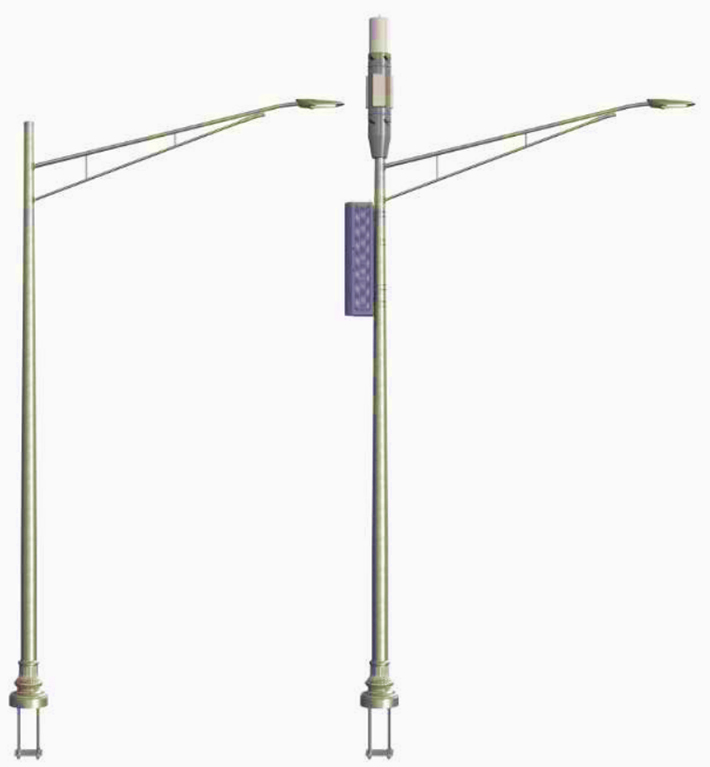
When adding loads from small cell equipment to a steel light pole, a combination of the utility industry, roadway lighting and the telecommunication industry design requirements need to be reviewed to determine the most stringent loading combination. When calculating the structural capacity of the pole the primary or intended use of the structure will determine the controlling design requirements. Examples of codes and standards to be considered are the NESC, AASHTO and ANSI/TIA-222-H. The attached Appendix A should be referenced for detail of a typical steel light pole configuration.
A. LOAD
i. Lighting structures tend to follow the AASHTO design series references which incorporate ASCE 7 loading criteria. The primary loading situation to consider is the wind loading which results in the greatest base moment reaction on a structure. The AASHTO series have been tailored to a pole structure by simplified means of gust factor calculations and standardization of urban terrain and exposure. However, the inclusion of telecommunications equipment and its unique shapes was not directly considered in the development of the wind loading portion of the specification. Therefore, the use of TIA design standards for these items would be appropriate. If overhead wiring is being applied, the NESC code should be used to determine the effect of that loading on the structure.
B. ANALYSIS
i. Depending on the code basis and methodology, the risk category for structures are considered by the use of different terms such as design life, recurrence interval, mean recurrence interval (“MRI”) or Risk Category. These terminologies are generally used to determine the wind velocity and importance factor to be utilized as it relates to the probability of a wind event to exceed a specific wind velocity in a given time frame. Depending on the code wind methodology (i.e. nominal or ultimate wind) different terminology is applied. In the ASD based AASHTO code, the design life is utilized to select the recurrence interval used to determine the importance factor (this is similar to the ANSI/TIA/EIA-222-F standard). A design life does not mean that the life of the structure will not extend past that period but should be looked at as the probably of a wind event exceeding the design wind in that time frame more likely than that of a longer design life callout. The LRFD AASHTO code has incorporated MRI to look at this same probability. Typical industry practice is that a steel light pole is designed for a 50-year design life (700year MRI) or 25-year design life (300-year MRI) based on design code and customer requirements. Rarely is it specified to have 100-year design life (1700-year MRI) or a high importance category. If this classification is required, clear direction from the customer would be required for the design to be completed. The process for analyzing the loading of a light pole is described within AASHTO Section 4 after loads are determined from other applicable codes. If there are questions on how to relate design life to MRI, reviewing the AASHTO code and the ASCE 7 transition history will provide comprehensive explanations on the differences. An understanding of this history is needed to make the best decisions in transitioning between different codes with differing methodology.
C. STRENGTH
i. Typical light pole components have detailed strength equations in AASHTO with modifications or simplification based on the structure in scope. The overturning moment tends to be the controlling portion of the strength check. Items that are not part of a typical light pole and have been specifically designed for telecommunication equipment, such as mounts, should look to the ANSI/TIA-222-H standard for guidance.
D. CONNECTION
i. There are many connections on a light pole both welded to bolted. The welding requirements of AASHTO are based off of AWS as a primary reference. The process to validate welds on a light pole should utilize AASHTO, or the governing light pole design code. Bolted connections have applicability in either code depending on the part in question. AASHTO focuses mainly on anchor rods and bolts for plate to plate connections such as an arm simplex to pole simplex. If the connection check is relative to mounts and u-bolting, as an example, the use of ANSI/TIA-222-H would be more appropriate.
E. MOUNTS
i. As described in the above breakouts, the mount should be under the scope of the ANSI/TIA-222-H.
F. SERVICEABILITY
i. The serviceability checks of both standards applicable based on the specific component under review. AASHTO references dead load deflection criteria for light poles with arms where ANSI/TIA-222-H references a twist and sway check and requirements for the space utilization of the interior of the shaft. Proper checks within both codes should be considered to ensure all requirements are satisfied.
G. MISCELLANEOUS
i. The review of the requirements relating to the key areas of a structure with lighting attachments (with or without transmission lines) and small cell equipment requires the use and cross-referencing of multiple codes to ensure all design are met in order to maintain public safety. Each design standard has specific items that apply to the intended use of the structure.
SECTION 3.5 TRAFFIC LIGHT/SIGN SUPPORT STRUCTURE
When adding loads from small cell equipment to traffic structures such as traffic lights and signs, a combination of AASHTO and ANSI/TIA-222-H, amongst other applicable codes, must be considered to determine the most stringent loading combination. In addition, items such as calculating fatigue stress is a standard practice for a traffic structure, but it isn’t a requirement for a telecommunications structure. When reviewing the structural capacity of a traffic structure, AASHTO shall be utilized relative to ANSI/TIA-222-H to ensure the stresses are within acceptable limits.
A. LOAD
i. Traffic structures tend to follow the AASHTO design series references which incorporate ASCE 7 loading criteria. The primary loading situation tends to be the fatigue load case but the design wind is also important for validation and anchorage design. The AASHTO series have been tailored to a pole structure by simplified means of gust factor calculations and standardization of urban terrain and exposure. However, the inclusion of telecommunications equipment and its unique shapes was not directly considered in the development of the wind loading portion of the specification. Therefore, the use of TIA design standards for these items would be appropriate. In the rare circumstances overhead wiring is being applied, the NESC code should be used to determine the effect of that loading on the structure.
B. ANALYSIS
i. Depending on the code basis and methodology, Risk Category for the structures are considered by the use of different terms such as design life, recurrence interval, and MRI. All four terminologies are generally being used to determine the wind velocity and importance factor to be utilized that relates to the probability of a wind event to exceed that wind velocity in a time frame. Depending on the code wind methodology utilized, the nominal or ultimate wind, the different terminology is utilized. A design life does not mean that the life of the structure will not extend past that period but should be looked at as the probably of a wind event exceeding the design wind in that time frame more likely than that of a longer design life callout. In the ASD based AASHTO codes, the design life is used to select the recurrence interval to determine the importance factor, which is similar to the ANSI/TIA/EIA-222-F code values. The LRFD AASHTO code have incorporated the MRIterminology accordingly. Typical industry practice is that a steel traffic pole is designed for a 50-year design life (700-year MRI). The process for analyzing the loading of a traffic pole is described within AASHTO Section 4 after loads are determined from other applicable codes. If there are questions on how to relate design life to MRI, reviewing the AASHTO code and ASCE 7 transition history will provide comprehensive explanations on the differences, this may be needed when make best decisions between different codes of differing methodology.
C. STRENGTH
i. Typical traffic structure components have detailed strength equations in AASHTO with modifications or simplification based on the structure in scope. The overturning moment tends to be the controlling portion of the strength baseplate and foundation check. For fatigue, the allowable limits at the welded shaft to transverse plate connections tend to be the limiting factor. In this situation, structures will be increased to account for proper fatigue designs that are not considered in ANSI/TIA-222-H. Items that are not part of a typical light pole and have been specifically designed for telecommunication equipment, such as mounts, should look to ANSI/TIA-222-H for guidance.
D. CONNECTION
i. There are many connections on a traffic structure both welded to bolted. The welding requirements of AASHTO are based off of AWS as a primary reference. The process to validate welds on a traffic structure should utilize AASHTO. The unique connections on a traffic structure, such as the gusseted arm to shaft connections, are standard traffic structure details that AASHTO has provided guidance on design in the standard. Bolted connections have applicability in either code depending on the part in question. AASHTO focuses mainly on anchor rods and bolts for plate to plate connections such as an arm simplex to pole simplex. If the connection check is relative to mounts and u-bolting, as an example, the use of ANSI/TIA-222-H would be more appropriate.
E. MOUNTS
i. As described in the above breakouts, the mount should be under the scope of the ANSI/TIA-222-H standard.
F. SERVICEABILITY
i. The serviceability checks of both standards applicable based on the specific component under review. AASHTO references dead load deflection criteria for traffic structures where ANSI/TIA-222-H references a twist and sway check and requirements for the space utilization of the interior of the shaft. Proper checks within both codes should be considered to ensure all requirements are satisfied.
G. MISCELLANEOUS
i. The review of the requirements relating to the key areas of a structure with lighting attachments (with or without transmission lines) and small cell equipment requires the use and cross-referencing of multiple codes to ensure all design are met in order to maintain public safety. Each design standard has specific items that apply to the intended use of the structure.
SECTION 3.6 BILLBOARDS – SMALL CELL
When adding loads from small cell equipment to a billboard a combination of the IBC and ANSI/TIA-222H should be utilized to determine the controlling load combination.
A. LOAD
i. Wind loads are addressed in IBC Section 1609. This section references the ASCE for wind load determination with some exceptions. Notably, that ANSI/TIA-222-H is to be used for antenna supporting structures.
B. ANALYSIS
i. Structure Classification
a. All billboards will be governed by the appropriate codes depending on the intended use of the structure.
b. Existing Billboard
b.i. If the intended use is to support existing display panel then the IBC and ASCE are used in the analysis of the structure. In cases where the display panel of the billboard is removed and its intended use is to support communications equipment, ANSI/TIA-222-H governs the analysis of the structure.
c. New Billboard
c.i. If the intended use is to support a display panel then the IBC and ASCE are used in the analysis of the structure. In cases where the display panel of the billboard is removed and its intended use is to support communications equipment, ANSI/TIA-222-H governs the analysis of the structure.
C. STRENGTH
i. Foundation
a. IBC Chapter 18 gives instruction on the design of foundations. Geotechnical investigations are encouraged, and presumptive soil values are also given.
ii. Steel Components
a. The design, detailing, fabrication, and erection of structural steel is covered in IBC Chapter 22. Anchor rods are specially addressed in this chapter and touched on briefly in IBC Annex H. Strength requirements should be in line with IBC Chapter 16.
D. CONNECTIONS
i. Billboards have many welded and bolted connections. IBC Chapter 22 gives direction on the design requirements for these types of connections. Connections uncommon to billboards and related to installation of telecommunication equipment should use ANSI/TIA222-H.
E. MOUNTS
i. Antenna mount
a. ANSI/TIA-222-H should be used.
F. SERVICEABILITY
a.i. The IBC gives serviceability requirements for several structural components in Section 16. The severability requirements should be applied to the applicable structural components of a billboard. ANSI/TIA-222-H also has serviceability requirements in Section 2.8 and Annex D which goes over twist and sway requirements for structures supporting microwave antennas. Both codes should be reviewed to ensure all requirements are satisfied.
CHAPTER IV
SUMMARY
The small cell market is an evolving area with all participants adapting to changing equipment, multi-use structure utilization and continually advancing regulations. The combination of this TIF White Paper and the individuals sound engineering judgement will provide the ability to identify the proper project design requirements. It is expected that most of the structures will be shared structures with other functions and the intended use will be the important determination for the project criteria. As design codes evolve and the industry matures, the users will have more guidance on how to work through these decisions. The new structures will be key to supporting the growing population and infrastructure so the sound engineering judgement to keep safety first in the designs will be critical.
Publication Date: November 16, 2020
© 2020 Telecommunications Industry Foundation
NOTICE OF DISCLAIMER AND LIMITATIONS OF LIABILITY
THE TELECOMMUNICATIONS INDUSTRY FOUNDATION (“TIF”) DOES NOT ENFORCE OR MONITOR COMPLIANCE WITH THE CONTENTS OF THIS DOCUMENT. ADDITIONALLY, TIF DOES NOT CERTIFY, INSPECT, TEST OR OTHERWISE INVESTIGATE PRODUCTS, DESIGNS OR SERVICES OR ANY CLAIMS OF COMPLIANCE WITH THE CONTENTS OF THIS DOCUMENT.
ALL WARRANTIES, EXPRESS OR IMPLIED, ARE DISCLAIMED, INCLUDING WITHOUT LIMITATION, ANY AND ALL WARRANTIES CONCERNING THE ACCURACY OF THIS DOCUMENT OR ITS CONTENTS, ITS FITNESS OR APPROPRIATENESS FOR A PARTICULAR PURPOSE OR USE, ITS MERCHANTABILITY AND ITS NONINFRINGEMENT OF ANY THIRD PARTY’S INTELLECTUAL
PROPERTY RIGHTS. TIF EXPRESSLY DISCLAIMS ANY AND ALL RESPONSIBILITIES FOR THE ACCURACY OF THE CONTENTS HEREIN AND MAKES NO REPRESENTATIONS OR WARRANTIES REGARDING THE CONTENT’S COMPLIANCE WITH ANY APPLICABLE
STATUTE, RULE, REGULATION, INDUSTRY STANDARD OR THE SAFETY OR HEALTH EFFECTS OF THE CONTENTS HEREOF OR ANY PRODUCT OR SERVICE REFERRED TO IN THIS DOCUMENT OR PRODUCED OR RENDERED TO COMPLY HEREWITH .
TIF SHALL NOT BE LIABLE FOR ANY DAMAGES, DIRECT OR INDIRECT, ARISING FROM OR RELATING TO ANY USE OF THIS DOCUMENT OR THE CONTENTS CONTAINED HEREIN,
INCLUDING WITHOUT LIMITATION ANY AND ALL INDIRECT, SPECIAL, INCIDENTAL, PUNITIVE OR CONSEQUENTIAL DAMAGES (INCLUDING DAMAGES FOR LOSS OF BUSINESS, LOSS OF PROFITS, LITIGATION, OR THE LIKE), WHETHER BASED UPON BREACH OF CONTRACT, BREACH OF WARRANTY, TORT (INCLUDING NEGLIGENCE), PRODUCT LIABILITY OR OTHERWISE, EVEN IF ADVISED OF THE POSSIBILITY OF SUCH DAMAGES. THE FOREGOING NEGATION OF DAMAGES IS A FUNDAMENTAL ELEMENT OF THE USE OF THE
CONTENTS HEREOF, AND THESE CONTENTS WOULD NOT BE PUBLISHED BY THE TELECOMMUNICATIONS INDUSTRY ASSOCIATION (“TIA”) OR TIF WITHOUT SUCH
LIMITATIONS. THE DOCUMENT IS TO BE USED FOR INFORMATION PURPOSES ONLY AND IS INTENDED TO PROVIDE AN OVERVIEW FOR EDUCATIONAL PURPOSES AND TO SOLICIT INPUT FROM THE INDUSTRY.
THIS DOCUMENT IS NOT A STANDARD. THIS DOCUMENT ONLY REPRESENTS THE COMMENTS AND OPINIONS OF THE AUTHORS AND IS NOT INTENDED TO SUPERSEDE, MODIFY OR INTERPRET ANY STATUTE, RULE, REGULATION OR OTHER INDUSTRY OR TIA STANDARD. THE PUBLICATION OF THIS DOCUMENT DOES NOT REPRESENT THE POSITION OR ENDORSEMENT OF TIA OR TIF.
ANTITRUST STATEMENT
THE TELECOMMUNICATIONS INDUSTRY FOUNDATION (“TIF”) SUPPORTS FULL COMPLIANCE
WITH ANTITRUST AND COMPETITION LAWS. ALL INDIVIDUALS WHO ASSISTED IN THE DEVELOPMENT OF THIS TIF WHITE PAPER AND ANY PARTICIPANTS IN MEETING CONVENED, ORGANIZED OR SUPPORTED BY TIF, INCLUDING BUT NOT LIMITED TO, THE PARTICIPANTS, TIF BOARD OF DIRECTORS, OFFICERS AND EMPLOYEES, TIF COMMITTEE MEMBERS, AND OTHER INVITED GUESTS (TOGETHER, THE “ATTENDEES”) ARE EXPECTED TO TAKE ALL REASONABLE MEASURES NECESSARY TO COMPLY WITH APPLICABLE STATE AND FEDERAL ANTITRUST AND COMPETITION LAWS.
ATTENDEES SHOULD NOT DISCUSS OR EXCHANGE INFORMATION OR DATA CONCERNING PRICING, TERMS AND CONDITIONS OF SALE AFFECTING PRICE, INDUSTRY PRICING POLICIES, MARKETING PROCEDURES, ALLOCATIONS OF FUNDS, CUSTOMER LISTS, RESTRICTIONS ON TYPES AND QUANTITY OF PRODUCTS AND SERVICES, REFUSALS TO DO BUSINESS WITH CERTAIN SUPPLIERS OR CUSTOMERS, OR OTHER SIMILAR TOPICS.
FURTHER INFORMATION CONCERNING TIF’S ANTITRUST POLICY IS AVAILABLE UPON REQUEST
AUTHORS:
Michael Cleary, PE – Maser Consulting; Kenneth Hill – Crown Castle; Xavier Jones – B+T Group; Scott Kisting – Proactive Telecommunications Solutions; Ashley Miller, PE – Trylon; Zach Thiemann Valmont Industries.
EDITORS:
Joshua Huff, J.D. – Tower Engineering Solutions; Michelle Kang, PE – Maser Consulting; Scott Stekr, PE Perfect Vision; Scott Vance, PE – B+T Group.
APPENDIX A: