Service Information
Drilled Pier Foundations
The drilled pier foundation design is used for monopoles, self supporting and guyed towers. Drilled pier foundations are capable of providing high load capacity. They are also referred to as drilled footings, drilled piers, drilled shafts, caissons and bored piles. The pier’s diameter and depth can be easily designed to match the load requirements with the specific geological site conditions. of providing high load capacity. They are also referred to as drilled footings, drilled piers, drilled shafts, caissons and bored piles. The pier’s diameter and depth can be easily designed to match the load requirements with the specific geological site conditions.
Using the correct loading, a structural analysis of the tower must be provided with base reactions in order for an engineer to provide a drilled pier foundation design. A geotechnical/soil report is normally required in order to obtain sealed design drawings for a building permit. The small amount of space required for drilled piers provides a favorable solution for installing a monopole or self supporting tower in confined lease areas, as long as the drill rig and service equipment have enough room to operate.
In soils in which drilled holes stand open easily, straight shafts are drilled very quickly, usually with an open-helix auger having two to three turns of a single flight. The auger may be equipped with either a knife-blade cutting edge or a series of replaceable cutting teeth.
Best progress is made with the blade when the auger is advanced fast enough to allow it to make a uniform cut, but not to corkscrew itself into the soil like an earth anchor, allowing the filled auger to be lifted without having to shear or tear the soil wall. The auger’s weighted pressure is called “crowd”. The rod that supports the auger when lowered or lifted is the “kelly” bar.
Belled or underreamed piers are piers with an enlarged base that are typically designed for additional uplift resistance or sometimes end bearing support. The base of the bell is usually no larger than three times the shaft diameter. The majority of monopole and tower designs are straight shafts.
The reinforcing cage is tied together, sometimes by a subcontractor of the drilling contractor, and then placed in the excavated hole with a crane or the drilling rig if the cage size can be accommodated. Proper clearance between the cage and the drilled hole is typically 3”. The top of the pier is normally formed between 6”-12” above ground level and the concrete is poured using a large tube with a funneled top known as a “tremie” pipe to reduce the vertical drop and prevent separation of the concrete mix if it were to hit the cage or walls.
Slump and maximum aggregate size must be specified to be sure that it will flow freely between the reinforcing bars and completely fill the space outside the cage. The anchor rod or anchor bolts are then placed in the concrete and properly aligned. Some site conditions require the foundation to be raised up to 12’ or more AGL for guy wire clearance or flood plane requirements. clearance or flood plane requirements.
The default pricing is a baseline of averages throughout the country for a drilled pier foundation in normal soil within 120 miles of the contractor’s office. The size of the foundation will influence the cubic yard pricing provided. Prices will vary based upon soil conditions, whether it is a wet or dry hole, if a casing is required, concrete design mix , slurry displacement, the project location and additional design requirements. If you're not utilizing the services of a drilling contractor, add concrete testing to your proposal. If your bid documents require you to provide a proposal using "normal soil" conditions, try to get the owner to provide soil borings with a report to ensure a competitive bid environment.
|
Drilled Pier Foundations
|
|
Monopole and Self Supporting Tower
|
In "My Estimator" enter the pier diameter and depth for total cubic yards and average baseline pricing based upon one pier for a Monopole, three piers for a Self Supporting tower. |
|
Guyed Tower
|
In "My Estimator" enter the tower base diameter and length, the anchor diameter and length and the number of anchors (3 or 6) for total cubic yards and average baseline pricing. |
We recommend that you contact our listed drilled pier foundation installation companies to obtain a quotation based upon the tower reactions and the soil borings provided, and to obtain additional information about their services, capabilities and experience.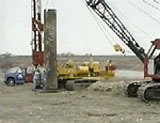
Casing and wet holes often required
A direct method of coping with caving cohesionless soils with or without high water tables is to use a steel casing that will later be pulled after the concrete is  poured. It is usual to drill the hole larger in diameter to allow for a 4” or more distance between the casing and the wall. When casing is practical, but difficult because of caving or seizing formations, the use of a vibrating pile driver can be very effective. poured. It is usual to drill the hole larger in diameter to allow for a 4” or more distance between the casing and the wall. When casing is practical, but difficult because of caving or seizing formations, the use of a vibrating pile driver can be very effective.
Wet holes using “slurry” can be used  where the water table is low but slightly clayey soils have a blocky or crumbly structure that leads to sloughing or caving. By adding water as the hole is drilled with a slurry mix it will produce a cohesive, remodeled soil on the sidewall of the hole, allowing the drilling to be completed without a casing. where the water table is low but slightly clayey soils have a blocky or crumbly structure that leads to sloughing or caving. By adding water as the hole is drilled with a slurry mix it will produce a cohesive, remodeled soil on the sidewall of the hole, allowing the drilling to be completed without a casing.
A slurry mix will allow a hole to be drilled in sand, dry, moist or saturated, with straight clean walls. It will also allow underreaming in clean sand below the water table.
The slurry’s viscosity must be high enough to prevent most suspended soil particles from settling out during drilling operations, but low enough that it will be readily displaced by concrete  placed by a tremie. Today’s slurry mixes are environmentally friendly and can be left on an unimproved tower site. However, some locations will require the displaced slurry to be hauled and properly disposed of off site. This is provided by the drilling contractor and will add to your installation cost. placed by a tremie. Today’s slurry mixes are environmentally friendly and can be left on an unimproved tower site. However, some locations will require the displaced slurry to be hauled and properly disposed of off site. This is provided by the drilling contractor and will add to your installation cost.
Equipment requirements vary
The type of drill rig required will vary based upon the diameter and depth of the pier design. Although a medium duty rig may be  capable of drilling the hole, a heavier rig may reduce the contractor’s cost per foot of the hole. The majority of drilling rigs are truck or carrier mounted, allowing for mobility traveling to and from and on the worksite. Most of them are equipped with rotating and sliding mounts, and the masts can be tilted for self-leveling and allows the capability to drill battered holes. The shaft diameter capable of drilling the hole, a heavier rig may reduce the contractor’s cost per foot of the hole. The majority of drilling rigs are truck or carrier mounted, allowing for mobility traveling to and from and on the worksite. Most of them are equipped with rotating and sliding mounts, and the masts can be tilted for self-leveling and allows the capability to drill battered holes. The shaft diameter  of drill rigs will vary based upon the manufacturer. Heavy duty rigs can auger a shaft between 18” to 84” in diameter and up to 60’ in depth. Some rigs can provide up to a 144” diameter drilled pier with a depth up to 100’ deep. of drill rigs will vary based upon the manufacturer. Heavy duty rigs can auger a shaft between 18” to 84” in diameter and up to 60’ in depth. Some rigs can provide up to a 144” diameter drilled pier with a depth up to 100’ deep.
To properly install a drilled pier foundation takes experienced personnel and the appropriate equipment. Wet holes are even more critical. Prior to selecting your drilled pier contactor you should ask for contacts for the firm’s most recent projects.
Soils set auger requirements
For drilling in soft materials to medium-hard rock, an auger is the most effective tool and drilling contractors will select the one that will allow for higher rotation drilling speeds which results in greater productivity and straight, true shafts. allow for higher rotation drilling speeds which results in greater productivity and straight, true shafts.
Single and double cutting edge augers are designed to be effective with minimum or no down pressure requirements. There are many augers available in the driller’s inventory from single flight, double flight and rock augers to mudding augers used to drill and mix cuttings into a slurry.
Cutting edges can be a blade or teeth or a combination of both. Drill buckets are used when drilling fluid and uncohesive materials will not stay on the flights of an auger. Bailing buckets will be frequently used for removing liquids contained in a shaft and cleaning the shaft bottom.
Core barrels utilize carbide teeth to excavate through extremely hard materials that cannot be efficiently drilled with an auger. Underreamers with either blades or cutting teeth are used to meet a variety of 45-degree or 60-degree belled shaft requirements. Soil conditions may require specialty tools such as boulder routers and extractors.
Shaft Areas and Volumes
|
Per Lineal Foot
|
|
Shaft Diameter
|
Volume
|
Side Shear Area
|
Bearing Area
|
|
Inches
|
Cubic Yards
|
Square Feet
|
Square Feet
|
|
12
|
0.03
|
3.14
|
0.79
|
|
14
|
0.04
|
3.67
|
1.07
|
|
16
|
0.05
|
4.19
|
1.40
|
|
18
|
0.07
|
4.71
|
1.77
|
|
20
|
0.08
|
5.24
|
2.18
|
|
22
|
0.10
|
5.76
|
2.64
|
|
24
|
0.12
|
6.28
|
3.14
|
|
26
|
0.14
|
6.81
|
3.69
|
|
28
|
0.16
|
7.33
|
4.28
|
|
30
|
0.18
|
7.85
|
4.91
|
|
32
|
0.21
|
8.38
|
5.59
|
|
34
|
0.23
|
8.90
|
6.31
|
|
36
|
0.26
|
9.42
|
7.07
|
|
38
|
0.29
|
9.95
|
7.88
|
|
40
|
0.32
|
10.47
|
8.73
|
|
42
|
0.36
|
11.00
|
9.62
|
|
44
|
0.39
|
11.52
|
10.56
|
|
46
|
0.43
|
12.04
|
11.54
|
|
48
|
0.47
|
12.57
|
12.57
|
|
50
|
0.51
|
13.09
|
13.64
|
|
52
|
0.55
|
13.61
|
14.75
|
|
54
|
0.59
|
14.14
|
15.90
|
|
56
|
0.63
|
14.66
|
17.10
|
|
58
|
0.68
|
15.18
|
18.35
|
|
60
|
0.73
|
15.71
|
19.63
|
|
62
|
0.78
|
16.23
|
20.97
|
|
64
|
0.83
|
16.76
|
22.34
|
|
66
|
0.88
|
17.28
|
23.76
|
|
68
|
0.93
|
17.80
|
25.22
|
|
70
|
0.99
|
18.33
|
26.73
|
|
72
|
1.05
|
18.85
|
28.27
|
|
74
|
1.11
|
19.37
|
29.87
|
|
76
|
1.17
|
19.90
|
31.50
|
|
78
|
1.23
|
20.42
|
33.18
|
|
84
|
1.43
|
21.99
|
38.48
|
|
90
|
1.64
|
23.56
|
44.18
|
|
96
|
1.86
|
25.13
|
50.27
|
|
102
|
2.10
|
26.70
|
56.75
|
|
108
|
2.36
|
28.27
|
63.62
|
|
114
|
2.63
|
29.85
|
70.88
|
|
120
|
2.91
|
31.42
|
78.54
|
|
126
|
3.21
|
32.99
|
86.59
|
|
132
|
3.52
|
34.56
|
95.03
|
|