Product Information
Base Station Antennas
When selecting the proper antenna for any application, several factors need to be considered. Typically, the most important characteristic of an antenna is its gain. Other factors include frequency, radiation pattern, electrical and mechanical downtilt, size, type, mounting requirements and feed horn placement.
By definition, an antenna is a device that focuses electromagnetic energy (RF) in a particular direction. By focusing this energy in any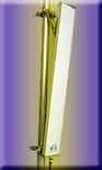 sort of direction other than just letting it radiate at random in all directions (visualize a point radiating in a sphere pattern, also known as an isotropic antenna) a “gain” is created in the direction the radiation is focused. sort of direction other than just letting it radiate at random in all directions (visualize a point radiating in a sphere pattern, also known as an isotropic antenna) a “gain” is created in the direction the radiation is focused.
It is not as complicated as it sounds. Imagine a certain amount of energy being focused in one direction, which leaves less energy to travel in other directions. The comparison or ratio of energy from the “particular direction” compared to all other directions gives us the antenna’s “gain”. Most antennas do not have built in amplifiers so there cannot physically be any “gain” in power from what is being transmitted by the radio, but the “focusing” process of the antenna takes this small amount of power and multiplies its effect by hundreds, if not thousands of times in the direction that the antenna is designed for.
 For budgetary considerations, the following prices are provided, based upon the list price average of multiple manufacturers. Tax and freight are not included. For budgetary considerations, the following prices are provided, based upon the list price average of multiple manufacturers. Tax and freight are not included.
|
Antenna
|
Frequency
|
Gain (dBd)
|
Gain (dBi)
|
Price
|
|
Fiberglass/Omni
|
806-896 Mhz
|
10
|
12.15
|
$1,318.00
|
|
Directional/90 D.
|
1850-1990 Mhz
|
15
|
17
|
$ 827.00
|
|
Dual Polarized/65 D.
|
1850-1990 Mhz
|
15
|
17
|
$1,244.00
|
We recommend that you contact our valued manufacturers and distributors for your site-specific antenna requirements.
Gain is but one aspect of antenna selection
The logarithmic scale based on the unit “decibel” is used to measure antenna gain. Every ten decibels, or dB, of antenna gain is the same as multiplying the power of the radio transmitter by ten. So a ten dB antenna will multiply the radio’s power by ten, a twenty dB antenna will multiply it by one hundred, etc.
Although gain is usually the key factor for selecting an  antenna, typically dictated by an overall system design and ultimately decided upon by an RF engineer, it is only one aspect. antenna, typically dictated by an overall system design and ultimately decided upon by an RF engineer, it is only one aspect.
Obviously, one must choose an antenna based on the frequency of the system that the user employs. In wireless, these antennas typically span one of several frequencies. Analog cellular, 800 MHz GSM, SMR (Nextel) and some paging systems typically use antennas that span from 800-950 MHz.
A-F band based PCS or other systems typically use antennas that span 1770-1990 MHz. Most current PCS providers use the frequency band of 1850-1990 MHz so the antennas that are chosen for this band usually are designed for this specific frequency range.
The next critical factor in choosing an antenna is radiation pattern. Typical radiation patterns range from 45 degrees for a directional antenna to 360 degrees for an omni directional, or “whip” antenna.
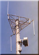
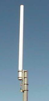
Many rural analog and digital cellular or SMR systems may employ an omni directional antenna that is usually 10’-20’ in length and radiates in all horizontal directions. Their vertical radiation pattern is usually 5-10 degrees.
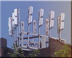 Most urban systems, and virtually all PCS systems, use directional, or panel, antennas. These antennas are used in a “sector” configuration, typically using a minimum of two antennas per sector aligned in a particular direction, usually trying to cover a specific area, or part of an overall sector-designed network. Most urban systems, and virtually all PCS systems, use directional, or panel, antennas. These antennas are used in a “sector” configuration, typically using a minimum of two antennas per sector aligned in a particular direction, usually trying to cover a specific area, or part of an overall sector-designed network.
Sometimes, panel antennas, especially using a high gain, narrow horizontal beam width, may be employed to enhance a very specific area. This may be used in a very hilly or mountainous area as one tries to enhance coverage down specific highway or street canyon corridors.
Downtilt critical to avoid interference
Electrical and/or mechanical downtilt is usually used in urban areas to limit the specific sites’ coverage to a limited area. Electrical 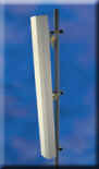 down tilt is built into the antenna and is ordered specifically for a particular site or overall system design. This feature is usually not field-adjustable, although some models do employ this feature. down tilt is built into the antenna and is ordered specifically for a particular site or overall system design. This feature is usually not field-adjustable, although some models do employ this feature.
Mechanical downtilt is the ability to physically tilt an antenna down from vertical, using antenna mounting hardware that allows this possibility. Most factory mechanical downtilt assemblies allow for anywhere from +2 degrees uptilt to -15 degrees downtilt. In both cases, this ability is crucial to avoid interference from adjacent sites in the same network.
 The next factor in choosing the proper antenna is size. As zoning and building permit restrictions have limited the overall size of antennas, this can be a crucial factor. Typically, “the bigger the better”, right? Mostly this is true, as far as gain is concerned. Usually the larger the overall cross section of the antenna, whether it is a directional or an omni antenna, the higher the gain of the antenna is. Many advancements have been made in this area, to squeeze out the most possible gain from the smallest possible antenna but, usually, bigger is better. The next factor in choosing the proper antenna is size. As zoning and building permit restrictions have limited the overall size of antennas, this can be a crucial factor. Typically, “the bigger the better”, right? Mostly this is true, as far as gain is concerned. Usually the larger the overall cross section of the antenna, whether it is a directional or an omni antenna, the higher the gain of the antenna is. Many advancements have been made in this area, to squeeze out the most possible gain from the smallest possible antenna but, usually, bigger is better.
As touched on earlier, the type of antenna, either directional or omni-directional, is an important factor in choosing the proper antenna. Usually the use of omni-directional antennas is limited to rural or poorly covered areas, whether PCS or cellular, as these antennas radiate in all directions. Very rarely are omni-directional antennas used in the PCS band, even in rural areas, due to the propagation properties of the higher frequency of PCS systems.
Connection point location is key in selection
The last two factors in considering the proper antenna is the mounting requirements and cable connection location. Almost universally, whether a panel or omni-directional antenna is  employed, they will mount to a vertical pipe, ranging in size from 2” O.D. (outside diameter) to 4.5” O.D. Some special mounting requirements can be accommodated by the factor but most have to be dealt with through the mount itself. employed, they will mount to a vertical pipe, ranging in size from 2” O.D. (outside diameter) to 4.5” O.D. Some special mounting requirements can be accommodated by the factor but most have to be dealt with through the mount itself.
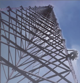
The location of the coaxial cable’s connection point is very important, especially involving directional antennas. Omni-directional antennas are almost universally fed from the very bottom of the antenna, with the coax or jumper connecting to the antenna vertically. Directional antennas, on the other hand, can usually be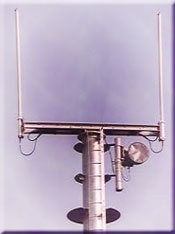 ordered to be top, bottom or back fed. Depending on what type of structure you are mounting the antenna to, one of these options needs to be considered. Most tower mounted antennas, whether guyed, self-supporting or monopole variety, usually are “back-fed” antennas, allowing the cable to connect to the antenna somewhere on the back of the antenna close to the center of the antenna vertically. ordered to be top, bottom or back fed. Depending on what type of structure you are mounting the antenna to, one of these options needs to be considered. Most tower mounted antennas, whether guyed, self-supporting or monopole variety, usually are “back-fed” antennas, allowing the cable to connect to the antenna somewhere on the back of the antenna close to the center of the antenna vertically.
The other options are used on antennas that are mounted to the side of a building or on a roof-mounted structure. Top-fed antennas can be employed on antennas that are mounted near the top of a building’s outer wall or parapet, where the cables come over the top of the parapet and go straight in the top of the antenna, creating a very clean, aesthetically pleasing installation.
 Bottom fed antennas may be used on a penthouse-mounting situation, where the coax comes up from the main roof surface or from behind the wall the antennas are mounted to and feed directly into the bottom of the antenna, again creating a very visually concealed installation. Bottom fed antennas may be used on a penthouse-mounting situation, where the coax comes up from the main roof surface or from behind the wall the antennas are mounted to and feed directly into the bottom of the antenna, again creating a very visually concealed installation.
|