
Installation Information
Dual Lighting Systems
FAA Type L864/L-865
The medium intensity dual lighting system has proven to be the ideal solution for densely populated residential areas. There are multiple designs for the flashhead beacon which eliminates the need for two separate lighting systems. A calibrated photocell will allow the system to automatically switch between daytime, twilight and nighttime intensities. Power converters are typically mounted at the base of the structure and monitor the operation of the system, providing alarm contact closure following any failure.
Although all dual lighting systems must meet FAA certification guidelines, not all systems offer the same product benefits.
 Average pricing to install an E-1 medium intensity lighting system (200’-350’) is $1,550. An E-2 System (351’-500’) is $1,950. Both prices are based upon the contractor erecting the initial structure and the client providing all materials on site. Average pricing to install an E-1 medium intensity lighting system (200’-350’) is $1,550. An E-2 System (351’-500’) is $1,950. Both prices are based upon the contractor erecting the initial structure and the client providing all materials on site.
We recommend that you contact our valued lighting installation professionals for your site-specific requirements.
Installation Checklist:
Each manufacturer has product-specific installation instructions and checklists, but by familiarizing yourself with these generalized instructions you can prevent costly failures and damage to the system.
Flashhead and Cable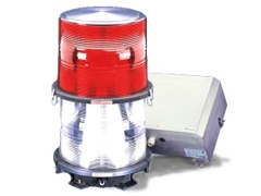
- DO NOT splice flashhead cable.
- Flashhead cable and power cable have their outer insulation jacket removed after entrance into the power converter cabinet.
- The flashhead cable insulation and power cable have not been nicked.
- The flashhead cable is properly secured to the tower so that the insulation will not be become cut with wind and oscillation.
- Secure the cable every 5’ or as required by the manufacturer and the NEC.
- Provide a service loop just below the flashhead.
- Ensure the flashhead cable is not pulled tight against sharp edges.
- The flashhead at the top of the tower has a lightning rod provided at least 18” above the top of the flashhead.
- The flashhead is mounted level. Some manufacturers provide leveling vials on the flashhead to assist with this process.
- The flashhead is grounded to the tower.
- The flashhead is mounted in an FAA approved location (no obstruction greater than 7/8” in the path of the horizontal beam).
- The flashhead wires are positioned so no arcing can occur and wire colors match the terminal designations.
- The flashhead is wired according to the manufacturer’s schematic.
Power Converter
- The power converter is mounted away from radio frequency interference.
- The power converter is mounted upright, is water tight and is lightning bonded to the site grounding system.
- The incoming service voltage and frequency match the data plate voltage on the power converter. All power converters should be powered from the same 20-amp breaker with nothing else on that breaker.
- All electrical connections and inside cabinet hardware mounts have been double-checked for tightness before powering up.
- All of the capacitor jumper wire connectors are installed correctly.
- The correct flashhead cable wire colors are connected and the shield wire is grounded on both ends.
- The intensity select switch is in the auto position.
- The photocell is connected to the master power converter and facing the northern sky per the FAA guidelines.
- All Master/Slave interconnect terminals are wired with a 16 AWG twisted pair at 12 twists/foot with polarity maintained. If the wire is shielded, ground one end only of the shield.
Premature failure of the lighting system can occur through incorrect generator usage.
It is extremely important to follow these rules if you are going to use a generator with any strobe lighting equipment.
- The generator is to be 5,000 Volt Amps (5 KVA) as a minimum for a single beacon and 7,000 Volt Amps (7 KVA) as a minimum for up to 3 beacons. In the event that a larger generator is used and other electrical components are also sharing this same power source, it is very important that the above specified minimum is always available for powering the tower lights.
- The generator is to supply power at 120 VAC, 60Hz sinewave.
- Square wave and quasi-sinewave output generators and UPSs should NOT be used.
- The wiring connecting from the generator to the power converter is to be sized as follows:
Up to 20 feet: 14 AWG, 3 conductor power cord
Up to 50 feet: 12 AWG, 3 conductor power cord
Up to 100 feet: 10 AWG, 3 conductor power cord
|