Default Design Parameters: 
You can simplify the structure procurement process by using the Standard’s default design parameters or you can identify the design that is appropriate for the structure’s location and intended service requirements.
You will be required to provide the county’s location, but it is also necessary to identify if the permitting jurisdiction has any additional design requirements or if the site is located in a special wind or ice region.
Classification of Structures:
The Standard establishes three classifications of structures based on reliability and/or hazard criteria. The default structure classification for new and existing structures is Class II.
The hazard to human life and damage to the property should be carefully considered in all categories since the hazard potential can override the type of service. In example, a taxi service tower, detailed as a Class l Structure, would become a Class III structure due to its location next to a hospital, day care center or any other environment where lives would be in danger if the structure failed.
The following descriptions indicate the appropriate classification for a new structure based on the type of service to be provided and/or the hazard potential:
Class I: Structures used for services that are optional or where a delay in returning the services would be acceptable such as: residential wireless and conventional 2-way radio communications; television, radio and scanner reception; wireless cable; amateur and CB radio communications.
These are structures that due to height, use or location represent a low hazard to human life and damage to property in the event of failure and/or used for services that are optional and/or where a delay in returning the services would be acceptable.
Class II: Structures used for services that may be provided by other means such as: commercial wireless communications; television and radio broadcasting; cellular, PCS, CATV, and microwave communications.
These are structures that due to height, use or location represent a significant hazard to human life and/or damage to property in the event of failure and/or used for services that may be provided by other means.
Class III: Structures used primarily for essential communications such as: civil or national defense; emergency, rescue or disaster operations; military and navigation facilities.
These are structures that due to height, use or location represent a substantial hazard to human life and/or damage to property in the event of failure and/or used primarily for essential communications.
Antenna / Line Loading and Structure Information:
A complete loading profile must be provided to the manufacturer or engineer for the structure that is to be designed. As a minimum the following details should be identified:
Structure type: (Monopole, Guyed Tower, Self Supporting Tower ) For guyed towers  provide the percentage of guy radius – typical design is 80% of the tower’s height – and elevation information if the anchors are not level with the base. provide the percentage of guy radius – typical design is 80% of the tower’s height – and elevation information if the anchors are not level with the base.
Structure height: (Provide height AGL plus identify if it is to be extendable and to what height)
FAA Lighting: (If required, specify the type: red lighting, medium intensity lighting, dual lighting , high intensity )
Painting: (If there are FAA requirements for painting, identify if it is to be factory applied)
Antennas: (Identify model number, if available, and if the antenna has a radome. Or provide the type of antenna and its effective projected area [EPA])
Antenna Heights / Locations: (Provide RAD center heights and azimuths)
Antenna Mounting Requirements: (Identify the type of mounting requirement such as 3’ side arm, low profile platform, t-frame, etc.)
Transmission Lines: (Detail the size of the transmission line or the manufacturer’s part number).
Transmission Line Attachment: (Provide details on the distribution of the antenna lines and the type of mounting hardware that will be used such as clusters or blocks. The Standard states that for latticed structures, all lines to a carrier elevation shall be considered to be on one face of the structure. It also says that it will be permissible to assume lines for different carriers are placed on adjacent faces of the structure.
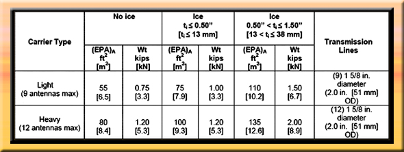
Typical Wireless Carrier Antenna Loading: When actual antennas and mounting details are undefined, the Standard provides for a typical (see below) wireless carrier loading consisting of multiple antennas mounted on a platform or similar
mount.
Basic Wind Speed and Basic Wind Speed with Ice
The structure will be designed to the Basic Wind Speed or the Basic Wind Speed with Ice that is derived from the Standard’s county by county listings. These values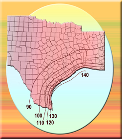 are taken from wind and ice maps prepared by ASCE. These maps are made by interpolating between stations (usually airports) at which the wind and ice values are calculated, resulting in contour lines of equal wind speed and ice thickness. When there are two or more contour lines passing through a county, the minimum and maximum values are given. You will be required to assess the wind speed of your site’s location. It’s also necessary to check whether the structure is to be built in a special wind zone area or if the permitting authority requires a higher wind speed or ice thickness than provided for in the Standard. The Standard allows ice to be ignored in the ¼” thickness zones. are taken from wind and ice maps prepared by ASCE. These maps are made by interpolating between stations (usually airports) at which the wind and ice values are calculated, resulting in contour lines of equal wind speed and ice thickness. When there are two or more contour lines passing through a county, the minimum and maximum values are given. You will be required to assess the wind speed of your site’s location. It’s also necessary to check whether the structure is to be built in a special wind zone area or if the permitting authority requires a higher wind speed or ice thickness than provided for in the Standard. The Standard allows ice to be ignored in the ¼” thickness zones.
Exposure Categories
An exposure category that adequately reflects the characteristics of ground surface irregularities at the site shall be determined for the design of a communications structure.
The default exposure category is Exposure C.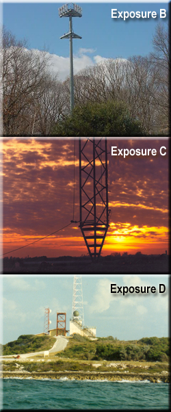
Account shall be taken of variations in ground surface roughness that arise from natural topography and vegetation as well as from constructed features. The exposure category for a structure shall be assessed as being one of the following:
Exposure B: Urban and suburban areas, wooded areas, or other terrain with numerous
closely spaced obstructions having the size of single-family dwellings or larger. Use of this exposure shall be limited to those areas for which terrain representative of Exposure B surrounds the structure in all directions for a distance of at least 2,600 ft [800 m] or twenty times the height of the structure, whichever is greater.
Exposure C: Open terrain with scattered obstructions having heights generally less than
30 ft [9.1 m]. This category includes flat, open country, grasslands and shorelines in hurricane prone regions. Sites located in Exposure B terrain that are located further than two miles but less than twenty times the height of the structure from an Exposure D terrain.
Exposure D: Flat, unobstructed shorelines exposed to wind flowing over open water
(excluding shorelines in hurricane prone regions) for a distance of at least 1 mile [1.61 km]. Shorelines in Exposure D include inland waterways, lakes and non-hurricane coastal
areas. Exposure D extends inland a distance of 660 ft [200 m] or twenty times the height of the structure, whichever is greater. Smooth mud flats, salt flats and other similar terrain shall be considered as Exposure D.
Topographic Categories:
Wind speed-up effects at isolated hills, ridges and escarpments constituting abrupt changes in the general topography located in any exposure category, shall be  included in the calculation of design wind loads when: included in the calculation of design wind loads when:
- The hill, ridge or escarpment is isolated and unobstructed by other similar topographic features of comparable height for a radius of two miles measured horizontally from the point at which the height of the hill, ridge of escarpment is determined, and
- The hill, ridge or escarpment protrudes by a factor of tow or more above the surrounding terrain with a two mile radius, and
- The slope (vertical to horizontal ratio) of the topographic feature exceeds 0.10, and
- The height of the topographic feature is greater than or equal to 15 ft. for exposures C and D and 60 ft. for exposure B.
The topographic category for a structure shall be assessed as being one of the following:
Category 1: No abrupt changes in general topography, e.g. flat or rolling terrain, no wind speed-up consideration shall be required.
Category 2: Structures located at or near the crest of an escarpment. Wind speed-up shall be considered to occur in all directions. Structures located on the lower half of an escarpment or beyond 8 times the height of the escarpment from its crest, shall be permitted to be considered as Topographic Category 1.
Category 3: Structures located in the upper half of a hill. Wind speed-up shall be considered to occur in all directions. Structures located in the lower half of a hill shall be permitted to be considered as Topographic Category 1.
Category 4: Structures located in the upper half of a ridge. Wind speed-up shall be considered to occur in all directions. Structures located in the lower half of a ridge shall be permitted to be considered as Topographic Category 1.
Category 5: Wind speed-up criteria based on a site-specific investigation.
The default topographic category is Category 1.

Earthquake Design Considerations In High Seismicity Regions
Antennas and antenna supporting structures require special considerations of their response characteristics in regions of high seismicity. The provisions of this Standard provide design criteria to insure sufficient strength and stability to resist the effects of seismic ground motions for self-supporting and guyed antenna supporting structures. Earthquake effects may be ignored for structures assigned to structure Class I or for any structure located in a region where the earthquake spectral response acceleration at short periods (Ss) is less than or equal to 1.00. See: Seismic Data.

Structures Supported on Buildings or Other Structures:
The height of the supporting structure is to be included in the procurement specifications in order to properly determine design loads in accordance with the Standard. In addition, for guyed masts, the locations of the guy anchor supports are also to be identified.
Climbing and Working Facilities:
The Standard specifies minimum climbing facility and platform requirements for personnel that will be accessing the structure. The default classification of climbing and working facilities is Class B. If a Class A climbing and working facility structure is requested the manufacturer will be required to provide a minimum of 24” of clearance from the ladder as well as a regulated toe clearance distances. For structures with step bolts equidistant spacing will be required. See: Climber Safety Standards. for personnel that will be accessing the structure. The default classification of climbing and working facilities is Class B. If a Class A climbing and working facility structure is requested the manufacturer will be required to provide a minimum of 24” of clearance from the ladder as well as a regulated toe clearance distances. For structures with step bolts equidistant spacing will be required. See: Climber Safety Standards.
|
User
|
Class
|
|
Authorized (Basic) or
Competent (Skilled) Climbers
|
A
|
|
Competent (Skilled) Climbers Only
|
B
|
Copyright Wireless Estimator, Inc. Please request reprint permission.
NOTE: This generic, non-exhaustive overview is intended to serve as a useful starting point for research and analysis of the topics addressed. Proper training, professional knowledge and oftentimes licensing are required prior to anyone providing product design, selection, installation, and construction/development-related activities. This information is neither presented to instruct nor teach anyone in the proper or safe methods of any aspect of wireless design or construction. To ensure minimum exposure and to determine compliance for a safe working environment, you must obtain the advice and guidance of an industry professional. professional knowledge and oftentimes licensing are required prior to anyone providing product design, selection, installation, and construction/development-related activities. This information is neither presented to instruct nor teach anyone in the proper or safe methods of any aspect of wireless design or construction. To ensure minimum exposure and to determine compliance for a safe working environment, you must obtain the advice and guidance of an industry professional.
WARNING: Failure to meet these minimum requirements and appropriate compliance responsibilities can result in serious injury or death to you or your fellow workers. All aspects of wireless construction are hazardous by nature. You have the sole responsibility to act safely and with caution prior to performing any construction-related task. your fellow workers. All aspects of wireless construction are hazardous by nature. You have the sole responsibility to act safely and with caution prior to performing any construction-related task.
Update: 1.20.2015
|